Blend Door Actuator Removal and Installation


Having no interior heat on the 1997 to 1998 Lincoln Mark VIII is a common problem. The problem is a part that Ford calls A/C Electric Blend Door Actuator ( F7LZ-19E616-AD) that costs only about $25, but requires over 6 hours of labor to replace. The cost to install this part at a dealer is $600 to $900. It would be far better to make the part so it does not break so easily. It is advised to reinforce the part so that you may not need to replace this part so often. See Blend Door Actuator Reinforcement for a procedure to reinforce this part. The following procedure to remove the old actuator and install the new one takes 5 to 6 hours. With practice, you may be able to do it in 3 hours.

Procedure:

  1. Put the steering wheel in the furthest out and down position.
  2. Disconnect the battery ground cable. This is very important to prevent shorts or your airbags from going off.
  3. Put the parking brake on and shift the car into first. This is to allow better access to the instrument panel. Chock the wheels to prevent the car from rolling.
  4. Remove the panel with the rear window defroster button, by pulling back on it from the upper corners. Use your fingers to do this. Do not use a screwdriver as you will damage the panels. Unplug the defroster and the heated seat switches if so equipped.
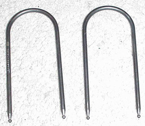
  5. Remove the radio using the special U-shaped Ford radio removal tool that fits into the four holes in the front of the radio. Put the tools in until they click, then push them laterally and pull towards yourself. Remove the radio connections and antennae and put the radio aside.
  6. Remove the wood instrument panel center panel screws which are under the panel you just removed.
  7. Pull back on the inside of the wood instrument panel center panel to remove it. Unplug the ground wire of the panel by pressing in the small button.
  8. Remove the six screws under the panels for the center console support bracket.
  9. Remove the mobile phone if so equipped. Then remove the two screws under the rubber mat in the center console glove compartment.
  10. Carefully unclip the the rear of the gear shift selector housing from the floor console. This is very fragile, so work slowly and carefully.
  11. Disconnect the wiring harness for the cigarette lighter and center glove box light and then remove the center console by pulling it back and up.
  12. Remove the two screws on the underside of the driver's lower instrument panel. Pull back the lower instrument panel to remove it.
  13. Disconnect the three steering column electrical connectors.
  14. Remove the four nuts on the underside of the steering column. Remove the u-shaped column retaining rod and the steering column over-travel prevention cables which are held down by the nuts closest to the driver.( If you do not have the steering column over-travel prevention cables, then you need to have them installed to prevent future expensive problems with the steering tilt mechanism. The cables were part of a recall by Ford. It should be no charge to install them by the Lincoln dealer.)
  15. Allow the steering column to come down to rest on the lower instrument panel reinforcement bar. I kept the lower duct in place with no resulting damage.
  16. Remove the two screws of the upper instrument steering column cover that are located on the instrument cover and remove the screws.
  17. Remove the headlight switch knob by pulling it back.
  18. Grasp the the left side of the headlight switch panel and remove it. Do not use a screwdriver as you damage this panel. Twist out the mini-bulb connector on the underside of this panel.
  19. Release the clips of the instrument dimmer switch. Pull out the dimmer switch and disconnect the electrical connector.
  20. Remove the two screws on the headlight switch panel base.
  21. Remove the two screws on the top underside of the instrument panel. Pull the instrument cluster finish panel back.
  22. Pull up on the front of the plastic door sill panels until the they unclip . The sill panels do not need to be completely remove. Just the front needs to be unclipped.
  23. Remove the left and right cowl kick panels by pulling back on them.
  24. Remove the left and right roof side inner front moldings by unclipping them. Unclip the mobile phone speaker on the left molding if so equipped.
  25. Using your fingers, lift the rear of the rear edge of the instrument panel defroster grille opening. Disconnect the A/C sunload sensor on the right side of the panel. Pull back the panel to remove it.
  26. Remove the three back pushpins on the underside of the glove box which hold up the black instrument panel insulator. Disconnect the courtesy light by twisting it and remove the black instrument panel insulator.
  27. Unhook the cable on the right side of the glove box by sliding the cable clip out of the notched slot on the glove box Remove the three screws holding the glove box hinge to the instrument panel. Remove the glove box.
  28. Remove the two left hand instrument panel 15 mm cowl nuts. One is located under the kick panel. The other is about six inches deep in the instrument panel. You can access it with a socket wrench with a 6 to 8 inch extension.
  29. Remove the two center instrument panel support nuts located in the center front near the floor under the removed center panels.
  30. Remove the two bolts and the bracket that connects the instrument panel to the floor on the drivers side near the forward edge of the console.
  31. Remove the one right hand instrument panel 15 mm cowl bolt located under the right side kick panel that was removed.
  32. Remove the six instrument panel top cowl bolts which are located under the cowl defroster grille panel that was removed.
  33. Now comes the big part. Pull the entire instrument cowl back about three inches on the right and an inch on the left.
  34. Now look through the opening from which the glove box was removed towards the front and center. You will see a gray door control lever. This the lever that you can pull down a little when then the blend door actuator arm breaks to get some heat. This will not work if the blend door actuator has completely come off the shaft of the motor. The gray arm works in tandem with the black arm of the blend door actuator via the flat long connector that holds them together.
  35. Remove the four screws that hold down the A/C Electric Blend Door Actuator. Three of the screws are visible. The fourth one is in the upper left hand corner. A 1/4 inch ratchet wrench is useful for removing these screws. I also found that a 5/16 inch GearWrench worked great for getting at the hard to get screws to remove and then later install them in the new Blend Door Actuator.

  36. You will find that the A/C Electric Blend Door Actuator comes out leaving the arm with the broken shaft still attached to the long flat connector between the arms. Remove the electrical connector from the A/C Electric Blend Door Actuator. Pull out the broken black door arm out of the hole of the blend door. Carefully bend out the end of the back arm to remove the post of the back arm from the long flat connector.
  37. Position the new A/C Electric Blend Door Actuator under the dash in the correct orientation. Connect the electrical connection.
  38. Carefully attach the long flat connector onto the black arm of the new A/C Electric Blend Door Actuator by bending back the clip retainer of the black arm.
  39. Reinstall the screws attach the A/C Electric Blend Door Actuator.
  40. Push back the instrument panel cowl. Use a screwdriver to pull back the left and right front weather-stripping over the cowl on each side. Start from the top and move the screwdriver down in a smooth motion.
  41. Reverse the steps above to reinstall all the parts you removed. Torque the four nuts on the underside of the steering column to 26 to 33 ft-lb. Torque the left and right instrument cowl nuts to 40 to 52 ft-LB Torque nuts holding the instrument panel to floor bracket to 20 to 24 ft-LB Torque The instrument panel center support nuts to 8 to 10 ft-LB
Return to Technical Help
Return to home


{main}